
Overview
Your students first learn about, then build simple circuits. Then they measure the voltage, and draw diagrams of the circuits they’ve created.
Instructions
What you'll need
Each group will need:
- Chart paper and markers
- A dry cell (battery) and holder
- Conducting wires
- A light bulb
- A switch
- A voltmeter
- “Exploring simple circuits” worksheet for each student
- "Lab investigations and safety" rubric
Safety first
- There must be a load in the circuit, like a light bulb, to limit the flow of electrons.
- Disconnect the circuit immediately if:
- It gets too hot, which indicates there is too much current flowing through the circuit.
- There is a short circuit.
Introduce simple circuits
- Begin a discussion about electrical circuits to gauge what your students know. Make sure they understand the symbols that are used in circuit diagrams.

Building a circuit
- Divide your students into groups and have them follow the instructions on their worksheets to construct their circuits.
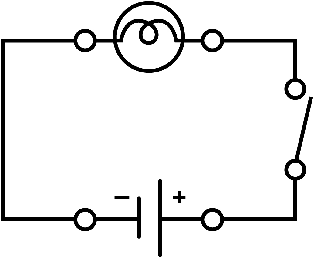
- Instruct your students to use the diagram in their worksheet to guide their circuit. Encourage them to observe the intensity of the light.
- Next, have students use a voltmeter to measure the voltage of each circuit. The voltmeter must be connected in parallel (it creates a second pathway for current flow) to the source (dry cell) or the load (light bulb). Have students record the voltage on their worksheets.
- Encourage your students to change their circuit design and observe the effect. They should draw a diagram of the circuit and record its voltage on their worksheets.
- Pair up the groups of students and let the larger groups combine materials. Have them measure the voltage of the new circuit before recording it and drawing the circuit.
Discuss and debrief
- Gather your students to discuss their observations. Have the groups share their diagrams and voltage measurements.
Modify or extend this activity
Extensions
- Consider getting your students to attempt a lemon circuit demonstration to further explore the key concepts of electrical current and circuits. Use copper wire for the experiment.
- Don’t use pennies because since the early 1980s they mostly consist of zinc.
- Continue exploring electrical currents with "Investigating series and parallel circuits", then challenge your students with "Investigating resistance".
Curriculum Fit
Grade 9 Science
Content
- Voltage, current and resistance
- Circuits
Curricular competencies
Questioning and predicting
- Demonstrate a sustained intellectual curiosity about a scientific topic or problem of personal interest
- Make observations aimed at identifying their own questions, including increasingly complex ones, about the natural world
Planning and conducting
- Collaboratively and individually plan, select, and use appropriate investigation methods, including field work and lab experiments, to collect reliable data (qualitative and quantitative)
- Ensure that safety and ethical guidelines are followed in their investigations
Processing and analyzing
- Seek and analyze patterns, trends, and connections in data, including describing relationships between variables (dependent and independent) and identifying inconsistencies
- Use knowledge of scientific concepts to draw conclusions that are consistent with evidence
- Analyze cause-and-effect relationships
Evaluating
- Evaluate their methods and experimental conditions, including identifying sources of error or uncertainty, confounding variables, and possible alternative explanations and conclusions
- Describe specific ways to improve their investigation methods and the quality of the data
Applying and innovating
- Transfer and apply learning to new situations
- Generate and introduce new or refined ideas when problem solving
Communicating
- Communicate scientific ideas, claims, information, and perhaps a suggested course of action, for a specific purpose and audience, constructing evidence-based arguments and using appropriate scientific language, conventions, and representations
- Formulate physical or mental theoretical models to describe a phenomenon
Assessments
- You can use the “Lab investigations and safety evaluation" rubric to guide your observation and assessment of your students during the activity.
Worksheet answer key:
Observations
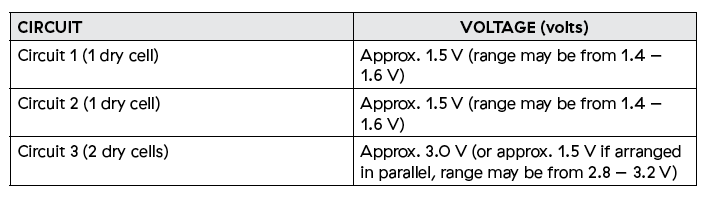
Table B
Analysis
- An electric circuit is a continuous path through which electricity can flow. Circuits are commonly found in devices that use electricity to perform tasks, such as powering a light source or providing heat.
- The three parts of an electric circuit are:
- An energy source, like a dry cell or battery, provides energy.
- A load, like a light bulb or resistor, is the object that uses the available electricity.
- A conducting material, like a wire, that connects the energy source to the load and provides a path for the electricity to flow.
- A switch is an optional fourth component that can be used to open or close the circuit.
- Successful circuits contain all three essential parts of a circuit configured in a closed loop. Successful circuits may differ in how they are configured:
- The different components may be arranged in a different order.
- The circuit may include more than one of any essential component, like two light bulbs instead of one.
- The circuit may include one or more non-essential components like a switch.
- If the circuit is a series, the voltage measurements are the same: Approximately 1.5 V when one dry cell is used and approximately 3 V when two dry cells are used. If the circuit is a parallel, the voltage will remain approximately 1.5 V.
- Answers will vary. Good examples include appliances that are plugged in, like televisions, computers, lamps and refrigerators. Some students may also describe the electrical system of the entire home as a system of circuits. All circuits work by providing a closed loop that enables electric current to flow.
Conclusions
- Students should provide a reasonable explanation of how they created functioning circuits and they should report on the accuracy of their prediction. They should also provide some ideas of how circuits are used in the real world.
Teaching Notes
An electric circuit provides a continuous path for electricity to flow through. There are three parts to an electric circuit:
- An energy source, like a dry cell or battery, provides energy.
- A load, like a light bulb or resistor, is the object that uses the available electricity.
- A conducting material, like a wire, that connects the energy source to the load and provides a path for the electricity to flow.
- A switch is an optional fourth component that can be used to open or close the circuit.
The flow of electric particles is called electric current. Only the negatively charged particles, electrons, move through a circuit. Electric current refers to the amount of charge that passes a point in a circuit in a given time. The unit of measurement for electric current is the ampere (A), named after the French physicist André-Marie Ampère.
The typical amount of current flowing through a 100-watt incandescent light bulb is 1 A. CFL and LED bulbs use considerably less current. An average TV set draws 3 A of current, while a starter motor in a car uses 500 A. We can use an ammeter to measure the amount of electric current at any point in a circuit.
Each electron has electric potential energy. We can measure the electric potential difference, the increase or decrease in electric potential energy, by measuring the electric potential energy per coulomb of charge. A coulomb is the charge transported by a steady current of 1 ampere in 1 second. Electric potential difference, the amount of electric potential energy in every coulomb of charge, is called voltage, is measured in volts (V), and is measured by a voltmeter.
A voltmeter can be connected across a component in a circuit to measure voltage. Note that the voltmeter is connected in parallel to the component (providing an alternative path for the current) so that a small amount of current goes through the voltmeter and the rest of the current goes through the circuit path. Voltmeters can be either analog or digital. A multimeter can also be used to measure voltage.
When an electric current enters a load it converts that electrical energy. A light bulb converts electricity into heat energy and light energy.

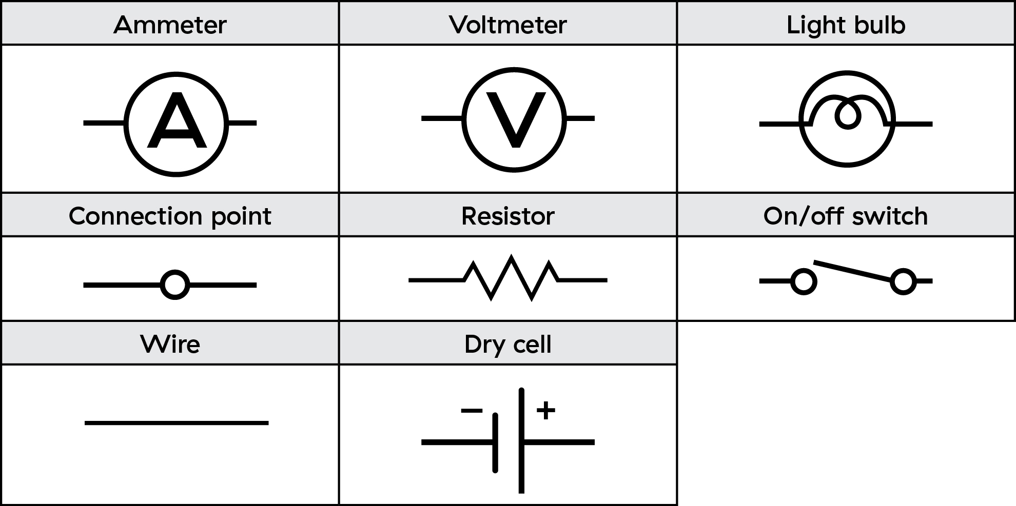
Circuit diagrams use a universal set of symbols, so can be understood anywhere in the world. The symbols also make it easier to draw complicated circuit diagrams showing different components.
Activity Materials
Select what you need below.
135.7 kb • pdf
301.3 kb • pdf