Investigating resistance
Explore the concept of electrical resistance by creating series and parallel circuits with a variety of resistors.


Overview
Students demonstrate how the resistance of a circuit varies when resistors are placed in series versus parallel. They complete calculations based on their group’s data.
Instructions
What you'll need
Each group will need:
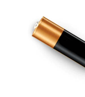
- 2 dry cell holders
- 2 dry cells
- 3 resistors, each with different values (between 100 and 1,000 ohms)
- Switch
- Connecting wires
- A voltmeter
- An ammeter
- "Investigating resistance" worksheet for each student
- "Lab investigations and safety" evaluation rubric
Ohm’s Law and resistance
- Introduce the purpose and procedure of the activity. Use the "Investigating resistance" worksheet to guide your class discussion.
- Review the safe use of voltmeters and ammeters with your students. If you have already taught this, ask your students to explain the concepts to their classmates.
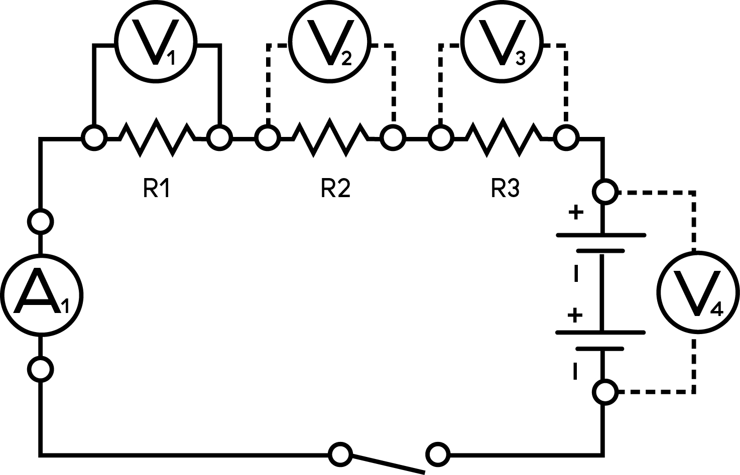
- Put your students into groups of three or four. Have them create series and parallel circuits as shown here. These schematics are the same as on their worksheets.
Series circuit - testing points
Parallel circuit - testing points
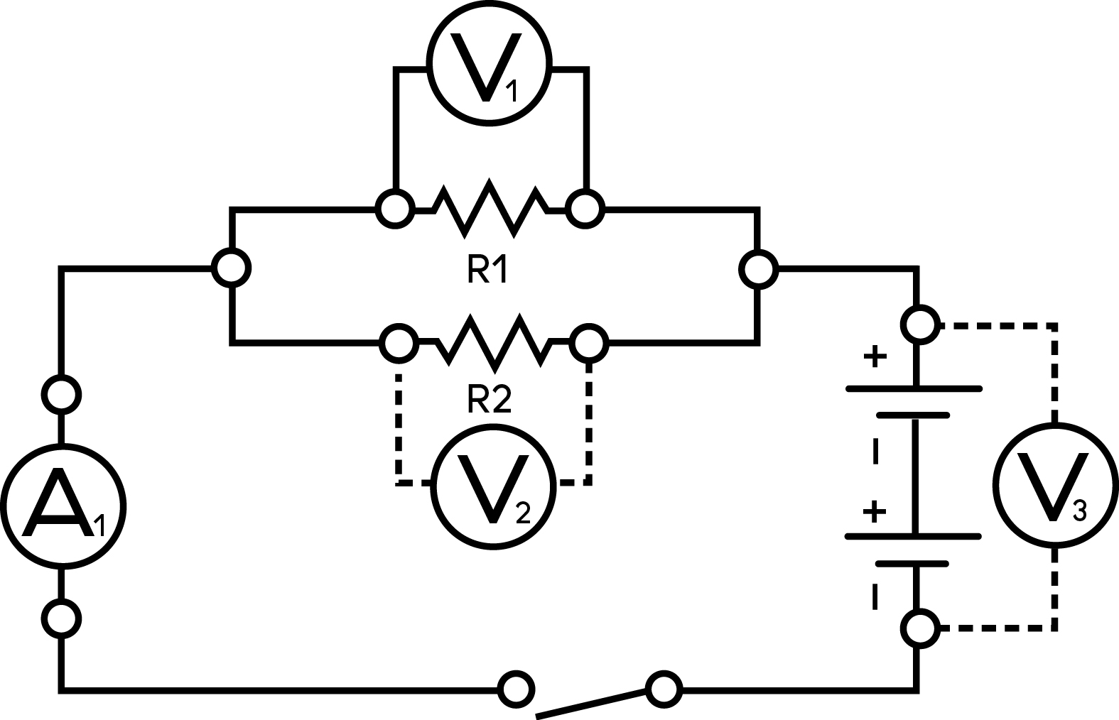
- Have students add one, two and three resistors to their circuits. They should measure the voltage and current at each resistor.
- Remind the students they also need to record the terminal voltages, the voltages across each resistor and the current through each resistor.
- Make sure your students are recording their data on their "Investigating resistance" worksheet.
- In their groups, have students complete the analysis questions on their worksheets.
- Bring the class together to discuss any patterns your students observed when measuring the voltage and current.
Modify or extend this activity
- After the students have completed the activity, present the “Introducing resistance” activity to recap the key concepts.
- The circuit activities in “Exploring Ohm’s Law” and “Solving Ohm’s Law” further explore these concepts.
Curriculum Fit
Grade 9 Science
Content
- Voltage, current and resistance
- Circuits
Curricular competencies
Questioning and predicting
- Demonstrate a sustained intellectual curiosity about a scientific topic or problem of personal interest
- Make observations aimed at identifying their own questions, including increasingly complex ones, about the natural world
Planning and conducting
- Collaboratively and individually plan, select, and use appropriate investigation methods, including field work and lab experiments, to collect reliable data (qualitative and quantitative)
- Select and use appropriate equipment, including digital technologies, to systematically and accurately collect and record data
- Ensure that safety and ethical guidelines are followed in their investigations
Processing and analyzing
- Seek and analyze patterns, trends, and connections in data, including describing relationships between variables (dependent and independent) and identifying inconsistencies
- Analyze cause-and-effect relationships
Evaluating
- Evaluate their methods and experimental conditions, including identifying sources of error or uncertainty, confounding variables, and possible alternative explanations and conclusions
- Describe specific ways to improve their investigation methods and the quality of the data
Applying and innovating
- Transfer and apply learning to new situations
- Generate and introduce new or refined ideas when problem solving
Communicating
- Formulate physical or mental theoretical models to describe a phenomenon
Assessments
- Observe students during the group work and use the "Lab investigations and safety" evaluation rubric to assess them.
Worksheet Answer Key:
Observations
Table A - Series Circuit Measurements
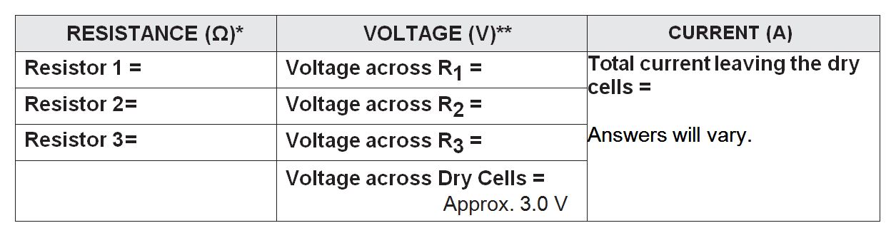
*Resistor values will depend on resistors used.
**Sum of the voltages across the three resistors should equal approximately 3.0 V.
Table B - Parallel Circuit Measurements
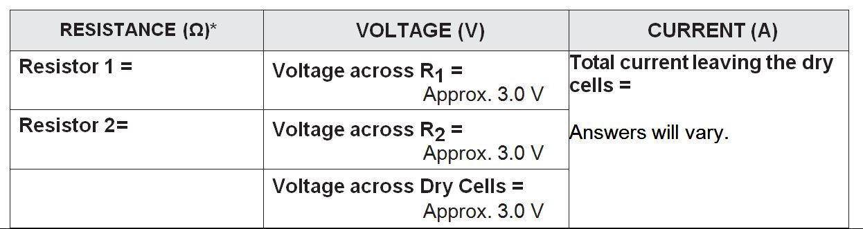
* Resistor values will depend on resistors used.
Analysis
1. Calculate the total resistance of your series circuit using Ohm’s Law (R = V / I). Be sure to use the voltage across the dry cells. Show your calculations.
- Answers will vary. R = ________________
2. How does the resistance calculated above compare to that of the individual resistors used in the circuit?
- Total resistance calculated above should be equal (or close) to the sum of the three resistor values.
3. How does the voltage compare across each resistor in a series circuit?
- The voltage is different across each resistor in a series circuit. Higher resistance yields higher voltage. The increase in voltage is proportional to the increase in resistance.
4. Add the voltages from across each of the resistors. How does this total compare to the voltage of the dry cells?
- The sum of the voltages across the resistors is equal (or close) to the total voltage of the dry cells.
5. Using Ohm’s Law, calculate the total resistance of your parallel circuit. Be sure to use the voltage across the dry cells as V in your calculation.
- Answers will vary. R = ____________
6. How does the resistance calculated above compare to that of the individual resistors used in the parallel circuit?
- The total resistance in the parallel circuit is less than any of the resistors used.
7. How does the voltage compare across each resistor in a parallel circuit?
- The voltage stays the same across each resistor in a parallel circuit.
Teaching Notes
Any electrical component with electrical resistance restricts the flow of electrons in a circuit and transforms electrical energy into other forms of energy.
A resistor is an electrical component with a specific resistance value. Resistors can be used to control current or to provide a specific voltage and current to other components in a circuit.
Students should use different strengths of resistors in their circuits. If the resistors have the same resistance value in a series circuit, the voltage drop in each resistor will be the same (each will be half of the applied voltage). For parallel circuits, the current will be the same through each resistor, although each will be half of the total current. Using resistors with different values emphasizes how the voltage and current change in series and parallel circuits.
Students should be able to recognize the following relationships emerging from the data collected during their investigations:
- The total resistance of a circuit depends on the number of individual resistances
- Increasing the number of resistors in a series circuit increases the total resistance and reduces the current
- Increasing the number of resistors in a parallel circuit decreases the total resistance and increases the current flow by creating additional pathways
Activity Materials
Select what you need below.
135.7 kb • pdf
529.7 kb • pdf