Investigating series and parallel circuits
Exploring the similarities and differences between the two types of electrical circuits.


Overview
After learning how to build series and parallel circuits, your students will use ammeters and voltmeters to compare voltage and current flow so they can understand the similarities and differences between the two types of electrical circuits.
Instructions
What you'll need
Each group will need:
- 2 dry cells (batteries) and holders
- Conducting wires
- 2 light bulbs
- A switch
- A voltmeter
- An ammeter
- “Investigating series and parallel circuits” worksheets for each student
- “Lab investigations and safety evaluation rubric”
Introduce series and parallel circuits
- Explain to your students the basic difference between series and parallel circuits:
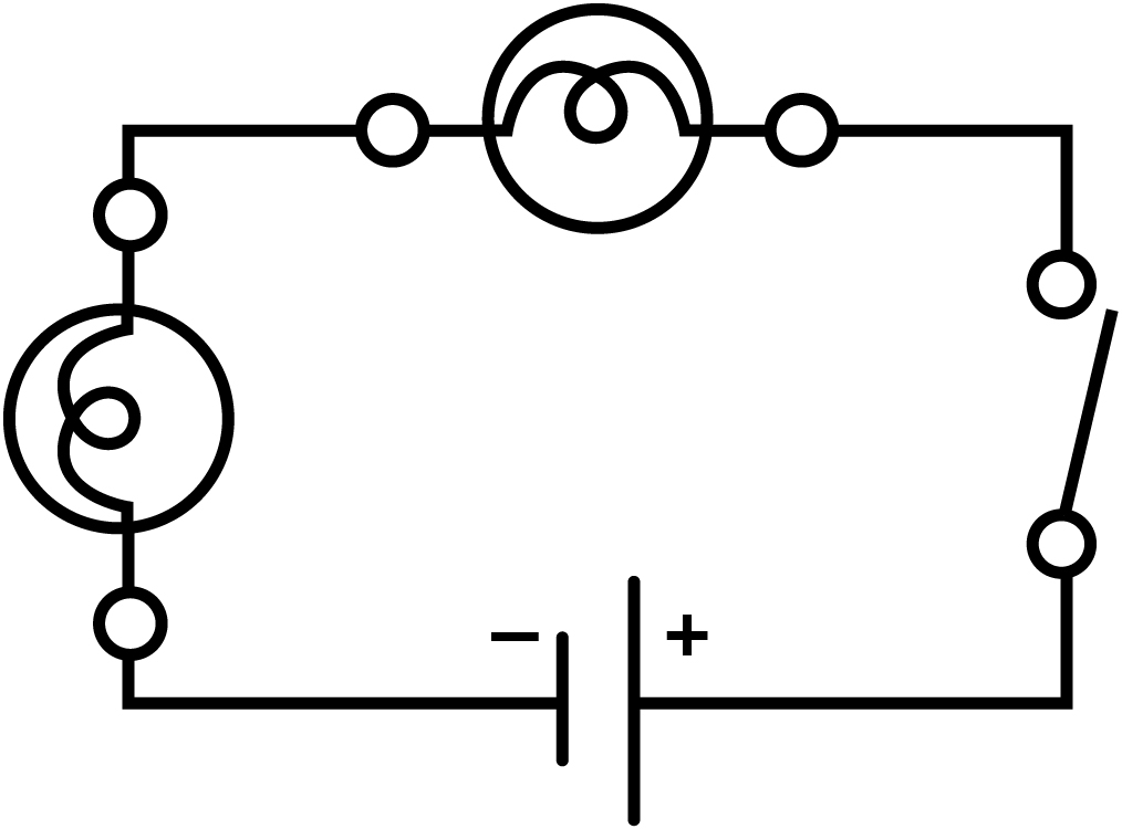
- In a series circuit, all loads, like light bulbs, are connected end-to-end, forming a single path for the current to flow.
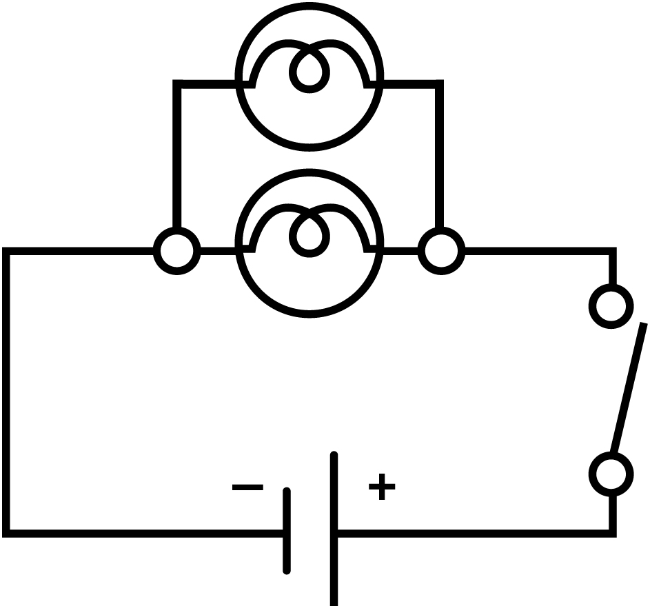
- In a parallel circuit, all loads are connected in parallel to one another, forming junction points where the current can split and combine.
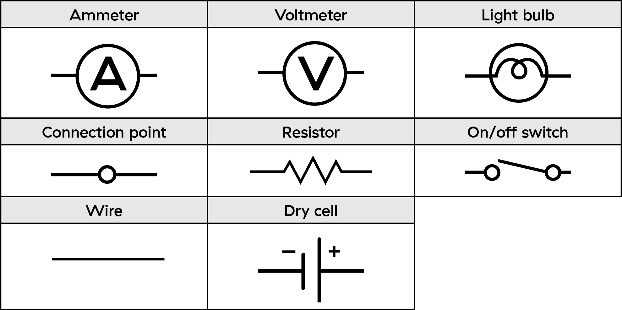
- Review the circuit diagram symbols on the first page of the “Investigating series and parallel circuits” worksheet with the students and clarify what the symbols represent.
Using the meters
- Demonstrate for your students how an ammeter needs to be connected in the path of the moving electrons, so it becomes part of the circuit.
- Demonstrate how the voltmeter must be connected in parallel to the dry cell or the light bulb as the voltmeter creates a second pathway for the current to flow.
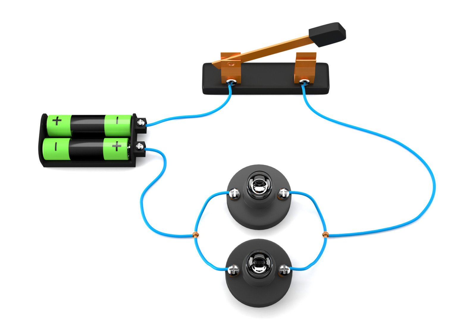
Build and test the circuits
- Put your students into groups and have them follow the instructions on their worksheets to build series and parallel circuits.
- You may need to circulate among the groups to ensure the ammeters and voltmeters are being used correctly as students test circuits.
- Remind your students to fill in their worksheet tables as they work through the steps of building the circuits.
- After you’re done, gather the class and have the students share their data and observations. Encourage the students to ask questions and review their data before you have them complete the analysis section of the worksheet.
Modify or extend this activity
- Have students do some thinking and research to come up with analogies for electrical circuits. For example, the flow of electrons can be compared to the flow of water.
- You and your students can continue exploring electricity and circuits with the activities “Introducing resistance” and “Solving Ohm’s Law”.
- Get your students to collaborate on a list of where, in the real world, electrical circuits are being used. Have them include the reason why series or parallel circuits are used. For example:
- Flashlights use series circuits so the light is bright in an emergency.
- TV remotes have batteries arranged in parallel so they last longer and don’t need a higher voltage.
Curriculum Fit
Grade 9 Science
Content
- Voltage, current and resistance
- Circuits
Curricular competencies
Questioning and predicting
- Demonstrate a sustained intellectual curiosity about a scientific topic or problem of personal interest
- Make observations aimed at identifying their own questions, including increasingly complex ones, about the natural world
Planning and conducting
- Collaboratively and individually plan, select, and use appropriate investigation methods, including field work and lab experiments, to collect reliable data (qualitative and quantitative)
- Ensure that safety and ethical guidelines are followed in their investigations
Processing and analyzing data and information
- Use scientific understanding to identify relationships and draw conclusions
- Seek and analyze patterns, trends, and connections in data, including describing relationships between variables (dependent and independent) and identifying inconsistencies
- Use knowledge of scientific concepts to draw conclusions that are consistent with evidence
- Analyze cause-and-effect relationships
Evaluating
- Evaluate their methods and experimental conditions, including identifying sources of error or uncertainty, confounding variables, and possible alternative explanations and conclusions
- Describe specific ways to improve their investigation methods and the quality of the data
Applying and innovating
- Transfer and apply learning to new situations
- Generate and introduce new or refined ideas when problem solving
Communicating
- Communicate ideas, findings and solutions to problem
- Formulate physical or mental theoretical models to describe a phenomenon
Assessments
You can use the “Lab investigations and safety evaluation rubric” to guide your observation and assessment of your students during the activity.
Worksheet answer key:
Observations
Analysis
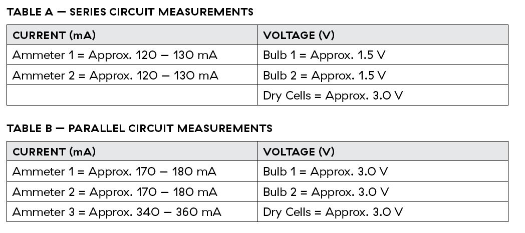
1. a) In the series circuit, the current measurements did not change (or were very similar).
b) In the parallel circuit, the current measured through each branch was approximately half of the total current measured at the dry cells.
2. In the series circuit the voltage across the bulbs is 3.0 V, while in the parallel circuit it's 1.5 V.
3. Voltage across the bulbs is approximately half of the voltage across the dry cells. Adding the voltage across the two bulbs is equal to the total voltage of the circuit.
4. Current running through the bulbs is approximately half the current running through the dry cells. Adding the current in the bulbs in the parallel branches results in the total current of the circuit.
Conclusions
The paragraph should include:
- In a series circuit, current stays the same throughout the circuit, but voltage decreases (is divided by the number of bulbs in the circuit as it is shared by each bulb).
- In a parallel circuit, voltage stays the same throughout the circuit, but current decreases and is shared as it takes different pathways through the circuit.
Teaching Notes
In series circuits, there is a single path for electricity to flow through the circuit. The electrons must pass through each of the loads in the circuit on their way back to the source.
When devices such as light bulbs are connected in a series circuit, the current goes through each device in sequence. The current at each point in the circuit is the same, and each load in the circuit uses some portion of the total source voltage. Older model holiday lights which have only one wire are a good example of a series circuit. When one bulb burns out it stops the current, and the rest of the bulbs cannot light because the circuit has been interrupted.
When devices are connected in a parallel circuit, the current divides evenly along the paths available. The voltage across each load in a parallel circuit is the same.
An ammeter measures the amount of electric current at a point in a circuit. An ammeter should be connected in the path of the circuit. For example, to measure the current through a light bulb, an ammeter should be placed in series with, or in the same path as, the light bulb.
The relationship between voltage and current in circuits is:
In a series circuit, the current remains the same but the voltage changes.
- In a parallel circuit, the current changes but the voltage remains the same.
A helpful way to remember this is:
- SASS: Series Amps Stay the Same
- PVSS: Parallel Voltage Stays the Same
Activity Materials
Select what you need below.
691.1 kb • pdf
135.7 kb • pdf
More activities from this unit